


 Home >
 Knowledge Base >
 Community >
 Downloads >
Establishing Commutation for Encoder-Halls Based Motors with the AKD/AKD2G
Commutation is the means by which a servo drive controls the torque of a motor by determining the position of the motor and applying current to the appropriate motor phases. If the rotor position of the motor is not determined correctly or the motor power phase wires are wired to the wrong terminals, the drive will apply current to the wrong phase at the wrong time (or at the wrong rotor position). This will cause the motor to run away or lock up.
The following is a procedure for determining the proper motor power wiring, encoder and hall signal wiring and commutation offset to allow the drive to correctly control the motor. This can be used in the case that the Commutation Alignment or Wake & Shake features don’t work successfully.
This document is specifically for the AKD drive but can also apply to most any brushless servo drive including the AKD2G.
-
AKD commutation offset parameter: MOTOR.PHASE
-
AKD2G commutation offset parameter: AXIS#.MOTOR.PHASE
-
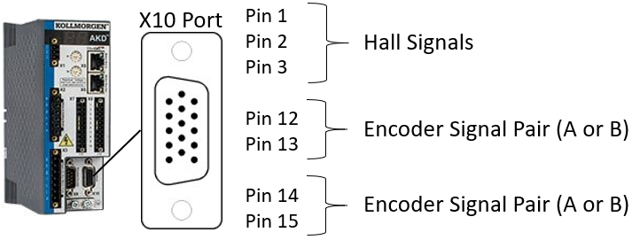
The encoder and hall feedback wiring for the AKD (X10 port) and AKD2G (X23 port or SFA) are identical.
See this procedure and accompanying flow chart as attached pdf's.
Ideal value of MOTOR.PHASE
-
Generates the highest speed for a given current command in torque mode.
-
Produces motion in the direction of the current command.
Assumptions
-
The AKD drive must be configured with the correct motor parameter settings and feedback settings.
-
Feedback must be functional.
-
There must not be any drive faults preventing the drive from being enabled.
Wiring
Since the encoder and hall wires are connected to the drive via the HD15 port, it is recommended to initially use a breakout terminal board for the feedback connections. This allows for much easier changes to the encoder and hall wiring.
-
The encoder wiring requirement is that each pair of encoder signals must be wired as a pair. This includes the A+/- and B+/- (or Sin+/- and Cos+/- for sine encoders). Refer to the installation manual for wiring and pinout information.
-
A+ paired with A-
-
B+ paired with B-
-
Sin+ paired with Sin-
-
Cos+ paired with Cos-
-
The UVW hall sequence must match the direction of the encoder. If the UVW hall sequence is backwards (WVU), the AKD will fault with F583 when the motor is moved. It can be corrected by swapping any two of the U, V, and W hall wires. It doesn’t matter which ones are swapped, since the commutation offset will account for the difference
-
Swapping encoder signals will change the direction of commutation.
-
Swapping A+ with A- will change the direction of commutation. This has a similar effect as swapping two motor power phases.
-
Swapping B+ with B- will change the direction of commutation. This has a similar effect as swapping two motor power phases.
-
Swapping the “A+/- pair” with the “B+/- pair” will change the direction of commutation. This has a similar effect as swapping two motor power phases.
-
When swapping encoder signals to change the direction of commutation, the hall signals may also need to be swapped.
Note: The direction of positive and negative motion is unrelated to the direction of commutation. The direction of motion can be configured independently using DRV.DIR (AXIS#.DIR for AKD2G) after commutation is established.
-
Swapping motor power phase wires affects the commutation offset.
-
The value of MOTOR.PHASE is relative to the feedback and motor phase wiring combination.
-
If you change the wiring by swapping any encoder +/- signals, both encoder A/B pairs, halls or any two motor power phases, you must find the corresponding value of MOTOR.PHASE.
-
Direction of motion can be corrected in software.
-
Don't be concerned about the direction of motion while establishing commutation.
-
The parameter DRV.DIR can be used to change the direction of positive and negative motion in software.
-
The default is DRV.DIR=0. If you need positive motion to move the other way, set DRV.DIR=1.
Safety – Overspeed protection
Set the overspeed fault threshold to a low speed (~800 rpm), in case of a runaway condition. Determine the appropriate threshold based on maximum motor speed and maximum allowable machine speed.
-
This is only to prevent the motor from spinning too fast and causing personal harm or damage to the motor or machine.
-
The overspeed fault threshold is monitored in torque mode, so setting the current setpoint too high will fault the drive almost immediately when the motor spins up.
Quick Procedure
-
Turn the motor by hand to verify PL.FB counts positive with the hall sequence U-UV-V-VW-W-WU. F583 will occur if the hall sequence is wrong.
-
If the hall sequence is backwards, swap any two hall wires. (Or swap the +/- of an encoder channel.)
-
Set the drive to torque mode and set an appropriate current setpoint. Adjust the setpoint throughout the procedure as needed.
-
Try different values for MOTOR.PHASE until the motor starts spinning in the direction of the current command.
-
If no values work, increase the current command or swap any two motor power phases.
-
Find the value of MOTOR.PHASE that generates the highest speed.
-
Test with a negative current command for opposite direction.
-
Test in Velocity mode or Position mode. Motion in both directions should use approximately the same amount of current.
Detailed Procedure
See the accompanying flow chart for a graphical representation of the procedure.
-
Encoder and Hall Direction:
-
The encoder must count positive along with the hall sequence U-UV-V-VW-W-WU. Turn the motor by hand to verify.
-
If the motor can’t be turned by hand, use a small current command in torque mode to move the motor. Remember that the motor may not be commutating correctly at this point and therefore could experience unexpected motion.
-
Fault F583 will indicate if the hall sequence is backwards. F583 will occur when motion is commanded or when the motor is turned manually while enabled in torque mode.
-
-
Reverse Hall Sequence:
-
If the hall sequence is backwards, swap any two hall wires. It doesn’t matter which ones since the commutation offset will account for the difference.
-
Alternatively, the direction can be changed by swapping the +/- of an encoder channel. For example, swap A+ and A-. Or swap B+ and B-. Or swap both A’s with both B’s. Any of these options will reverse the encoder counting direction.
-
-
Torque Command:
-
Set the drive to Torque mode.
-
Set a very small current setpoint (0.050 Arms for small motors).
-
You could use Service Motion or a digital input command buffer instead of setting IL.CMDU in the terminal. There are multiple ways to command current.
-
For large motors or frameless motors installed in a machine and unable to disconnect the load, use a higher current setpoint with caution.
-
-
Monitor current feedback (IL.FB) to verify that the drive is outputting the correct current.
-
-
Set MOTOR.PHASE:
-
Try MOTOR.PHASE values: 0, 90, 180, 270. If the motor starts spinning, adjust your current setpoint for appropriate speed (several hundred rpm, if appropriate for the motor). Note: When setting MOTOR.PHASE, as soon as you enter a value in Workbench that new value is active. There is no need to save or reboot the drive to test MOTOR.PHASE values.
-
If this works, skip to step 6.
-
-
-
If No Motion:
-
Note: If the motor will not spin with any values of MOTOR.PHASE (0, 90, 180, 270), either the current setpoint is too low or the motor phases are wired wrong.
-
Increase the current setpoint.
-
Try MOTOR.PHASE values: 0, 90, 180, 270. If the motor starts spinning, adjust your current setpoint for appropriate speed.
-
If this works, skip to step 6.
-
-
If no motion, repeat step 5.2 until reaching a considerably high current setpoint.
-
If this doesn’t help, reduce the current setpoint back to the previous value and continue to step 5.3.
-
-
-
Swap any two motor phase wires to reverse the commutation direction.
-
Try MOTOR.PHASE values: 0, 90, 180, 270. When the motor starts spinning, adjust your current setpoint for appropriate speed.
-
If no motion, increase the current setpoint.
-
Again, try MOTOR.PHASE values: 0, 90, 180, 270. When the motor starts spinning, adjust your current setpoint for appropriate speed.
-
Repeat step 5.3.2 until the motor spins.
-
-
-
Read velocity feedback to verify correct direction of motion.
-
Note: A positive current setpoint must produce motion in the positive feedback direction.
-
If the motor spins in the positive feedback direction when given a positive current, proceed to step 6.
-
If the motor spins in the negative feedback direction when given a positive current, set MOTOR.PHASE to +/- 180 degrees from the current setting.
-
The motor should now spin in the positive direction, given a positive current. Proceed to step 6.
-
-
-
-
Fine Adjustment of MOTOR.PHASE:
-
Adjust MOTOR.PHASE to find the value that gives the highest speed for a given current setpoint.
-
Increment MOTOR.PHASE by 10 degrees to find the value that increases the motor speed.
-
Continue incrementing MOTOR.PHASE until the speed starts decreasing.
-
Example: Motor spins with MOTOR.PHASE=270. Try MOTOR.PHASE=290 and MOTOR.PHASE=250. If speed decreases with 290, then it's getting farther out of phase. If speed increases with 250, then keep lowering MOTOR.PHASE until the speed starts decreasing. Try 240...230...220.
-
If 240 gives the highest speed and 230 or 220 starts slowing the motor down, then set it back to 240.
-
-
If the speed is noticeably affected by smaller changes in MOTOR.PHASE, then make finer adjustments to find the ideal value that gives the highest speed.
-
-
-
Test Opposite Direction:
-
Change the current setpoint to the negative of the previous value to verify the commutation works in the opposite motion direction. The positive direction speed and the negative direction speed should be approximately the same.
-
-
Test in Velocity Mode or Position Mode:
-
Set the drive to velocity mode or position mode. Command motion to verify the commutation.
-
It is possible to create motion in torque mode with MOTOR.PHASE set incorrectly. When switching to velocity mode, this can cause erratic motion, runaway, loss of torque, or poling.
-
Motion can be commanded via service motion, terminal commands, motion tasking, etc.
-
-
Tune the velocity loop to make sure the motor is stable and still commutating correctly. (Using the Performance Servo Tuner (Autotuner) is a good way to make sure everything is working.)
-
See the accompanying flow chart for a graphical representation of the procedure.
Back to top